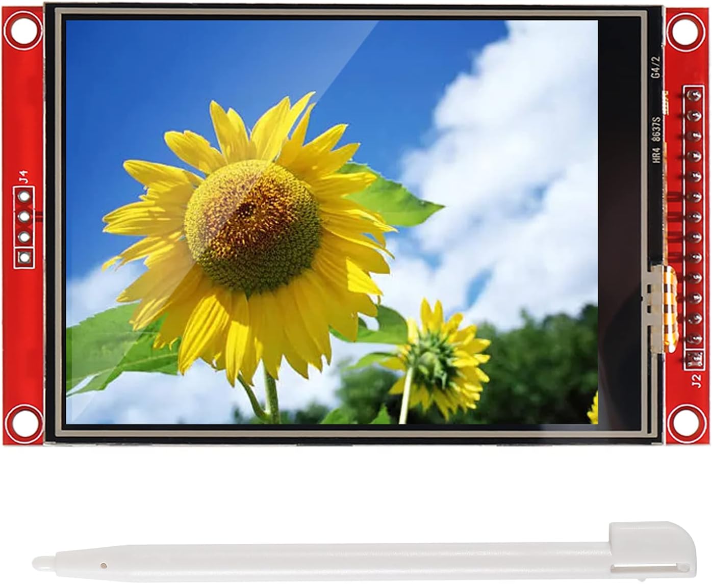


DIANN ILI9341 SPI TFT LCD Display Touch Panel (3.2")
Product ID: 518436634
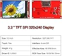
🎨320x240 RGB color pixels
💾Built-in SD card socket
📏3.2-inch vibrant display
Buy anything from 5,000+ international stores. One checkout price. No surprise fees. Join 2M+ shoppers on Desertcart.
Desertcart purchases this item on your behalf and handles shipping, customs, and support to Tunisia.
✨ Elevate your DIY projects with a splash of color and touch! 🎨
The DIANN ILI9341 is a 3.2-inch SPI TFT LCD touch display featuring a sharp 320x240 RGB screen, built-in ILI9341 driver, and an SD card socket for expanded storage. Designed for Arduino R3 compatibility, it offers bright backlighting and responsive touch input, making it ideal for professional-grade DIY electronics and prototyping.


| ASIN | B0BNQD38T2 |
| Brand | DIANN |
| Customer Reviews | 4.1 4.1 out of 5 stars (42) |
| Date First Available | 6 Jan. 2023 |
| Guaranteed software updates until | unknown |
| Item Weight | 50 g |
| Manufacturer | DIANN |
| Product Dimensions | 8.38 x 4.83 x 0.51 cm; 50 g |
C**N
Works well, but difficult to find good instructions on setup.
This display works great. Clear backlight, viewing angles are better than I expected, and the touch screen accuracy (although not perfect) is plenty good enough for what I'm using it for. My main gripe with this display is that it's real hard to find good instructions on wiring this thing up with a Raspberry Pi. That's probably to be expected given the price, though. For anyone else using a Pi, here's what I had to do: - This display has different SPI lines for the display and the touchscreen. You can tie both of them together (T_DO to SDO, T_DIN to SDI, T_CLK to SCK). You just have to make sure you have different CS lines for each of them. However, due to bus frequency differences, I'd recommend putting each on a separate SPI bus if you have the choice (my second one was already in use). - If you're using CircuitPython, you can't use the SPI0 CE0/1 pins for this -- pick any other GPIO pin. - The display library I used was adafruit/Adafruit_CircuitPython_RGB_Display on GitHub. - The touch panel library I used was humeman/xpt2046-circuitpython on GitHub. - When using the Adafruit display library, whenever you control the screen it updates the SPI bus frequency to 16M. This doesn't work for the touchscreen if it's sharing the bus -- I've found that anything around 1M causes lots of inaccurate readings. As a workaround for this, assuming you're using one SPI bus as I am, you can run: spi.try_lock() spi.configure(baudrate = 100000) spi.unlock() every time before you poll the XPT chip for touchscreen coordinates. - I'd recommend attaching a resistor (I used a 100 ohm one, some others recommend 56) to the LED line. You can change the value of this depending on the brightness you want. I've attached the pins I used as a picture.
B**T
Got what I ordered and in a reasonable time.
Hey, it just works. Decent touch screen, enabling custom soft buttons, or whatever you want. Bright enough for indoor use, haven't tried it in bright sum light. I haven't tried the SD card reader, however. It runs my Arduino application just fine. It was a drop in replacement to previous displays I ordered.
A**A
Failed Electronics (Junk)
Don't waste your money. This product does not work as advertised. I tried multiple ways to run it with Arduino UNO R3 and it did not even come on.
P**R
Good for the cost
This is a really good display for the cost. It's simple to hook up, and I've tried it out on several different MCUs. So here are some tips: Finding official datasheets on this display can be challenging unless you know what to search for. This board is known by its maker(s) as the MSP3218. You can find data on lcd wiki dot com. You want the page bearing the title 3.2inch_SPI_Module_ILI9341_SKU:MSP3218 and on that page are links to schematics, user guides, datasheets, the works. You may also find references to this display as "Red ILI9341" This product is really three things in one, a 320x240 TFT LCD Display controlled by the ILI9341, a resistive Touch Panel controlled by the XPT2046, and an SD card reader. All three can share the same SPI signals from the MCU (CLK, MISO, MOSI) but each uses a different CS (chip select) pin makes 6 wires. The display needs an extra DC wire, so this makes 7. The (optional) LED pin can always be on, connecting to 3V3, the (optional) RESET can be connected to the MCU (RST) reset, and the (optional) touch (T_IRQ) interrupt can be left unconnected. But if you opt to connect them to the MCU, that's a total of 10 (3V3 signal) lines plus 2 power lines. Note, this board designed for 3.3V (3V3) logic signals. Arduino Uno R3, Uno R4, Mega and some other MCU operate on 5.0V (5V0) TTL logic levels. To use this display on those boards, you MUST use some bi-directional "level shifters" in between the two to shift the logic signals between 5V0 and 3V3. ESP32, ESP32-S3 and some other MCU operate on 3V3 logic levels, so no level shifters are required. One symptom of the 5V0 over-voltage is a white screen, with no other obvious output. You power the Red PCB by its VCC/GND pins, and the docs say you use 3V3 or 5V0. But I have another tip, use 5V0 on the VCC. The schematics will show the Red PCB has a power regulator to regulate the 5V0 down the 3V3. If you supply it with 3V3 it still functions in SOME cases. It failed to operate with some MCU I've tried, unless I gave to 5V0. The SD Card is particularly sensitive to undervoltage, and may not work at all, unless it's getting a solid 3V3, which it can only do, if you supply the regulator with 5V0. Since the Arduino Uno is pretty common for people, I can offer the following connection schematic to get you up and running quickly. These pairing start with the Uno R3 signal, followed by the Red ILI9341 PCB signal name printed on the PCB. Uno 5V = VCC, Uno GND = GND, Uno RST = RESET, Uno 3V3=LED, Uno D13 = SCK+T_CLK+SD_CLK, Uno D12 = SDO(MISO)+T_DO+SD_MIDO, Uno D11=SDI(MOSI)+T_DIN+SD_MOSI, Uno D10=CS, Uno D09=DC, Uno D8=T_CS, Uno D7=SD_CS You're on your own installing libraries in Arduino IDE, there are several good ones out there. Google those chip names, and you should find what you need. I'm using Adafruit_ILI9341, and XPT2046_Touchscreen libraries. The SD library is built-in. Be patient, double check your connections, and enjoy this fun little display.
P**T
Works well
Worked well until I accidentally powered it with 12v from a boost converter that I thought was adjusted much lower. Not the product's fault, obviously.
Trustpilot
1 month ago
1 week ago