Desertcart purchases this item on your behalf and handles shipping, customs, and support to Tunisia.
🤖 Build, solder, and race your way to STEM mastery!
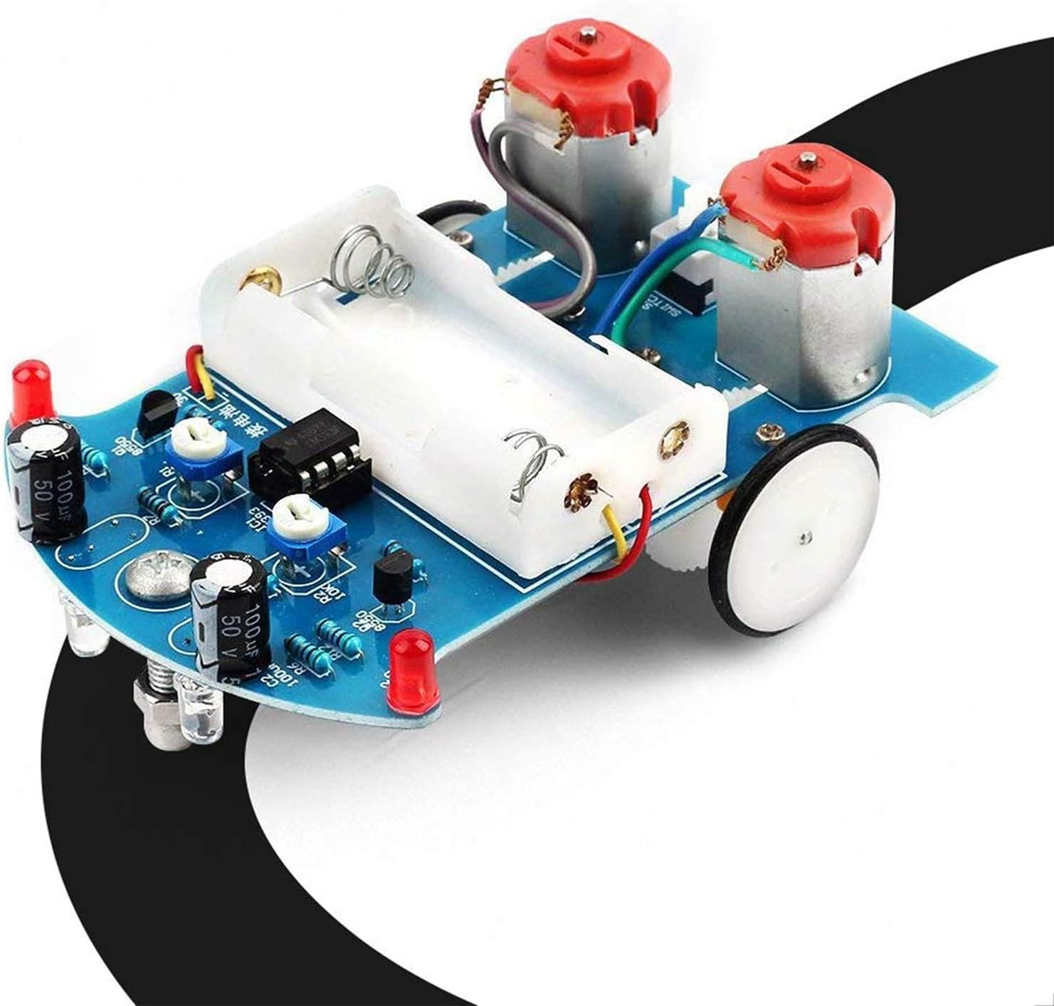
The MiOYOOW Line Following Robot Car Kit is a compact, beginner-friendly STEM educational kit designed for ages 13+. It features a smart line-following system using photoresistor sensors and a dual op-amp circuit, enabling autonomous navigation on custom black tape tracks. The kit promotes hands-on learning in electronics, soldering, and mechanical assembly, supported by clear instructions and downloadable manuals. Perfect for school projects, home learning, and sparking interest in robotics and engineering.


| ASIN | B0732Z1FZC |
| Age Range Description | over 15 years old |
| Battery Description | Alkaline |
| Best Sellers Rank | #62,208 in Toys & Games ( See Top 100 in Toys & Games ) #552 in Educational Science Kits |
| Brand Name | MiOYOOW |
| Customer Reviews | 4.2 out of 5 stars 649 Reviews |
| Educational Objective | electronic skills, mechanical skills |
| Included Components | circuit board |
| Item Dimensions | 4 x 2.8 x 0.06 inches |
| Item Weight | 2.4 ounces |
| Manufacturer | WHDTS |
| Manufacturer Part Number | 43234-1592 |
| Manufacturer recommended age | 13 years and up |
| Material Type | fiberglass |
| Model Number | 10168 |
| Number of Items | 1 |
| Set Name | Line Following Robot Car Kit |
| Size | Compact |
| Theme | Car,Robot |
| UPC | 615135207530 |
| Unit Count | 1 Count |
L**.
Neat little kit, great for starting out with electronics and soldering
Thought I'd try this little smart car kit, I built one long ago, wasn't as nice as this one though. The kit seems small at first, everything is in a little anti-static bag perhaps 3in by 5in (8cm x 13cm?). Spread the components out and it takes up a fair bit of space. Uh, don't do that though... my cat thinks red LED's are fun to bat around. Let's see... 8 resistors, two transistors, two 10K potentiometers, 4 LED's (2 kinds of red), 2 LDR's, 2 electrolytic capacitors, 2 motors, gear sets and wheels, one battery holder (2 AA) and clicky power button. An LM393 dual op-amp, a nice blue PCB, some wire and a handful of screws. Oh, and a bolt with nut and acorn nut to work as a 'caster' wheel. Plenty to do! The kit comes with a sheet of instructions, one side has an oval track on it so you can play with your smart car right away, while the other side has instructions for assembly, a parts list and a good schematic. If you download the 'Smart Car Instruction' PDF file, it expands on the assembly instructions with good quality color photos, allowing you to visually verify you've got things in the right places, right orientation (electrolytic caps, transistors, LED's and op-amp!). Very helpful. Assembly is straightforward, start with the lowest components (the resistors, usually), and solder them to the PCB as directed, paying attention to the silkscreen for LED & eCap polarity and others as needed. I suppose it took me about an hour, I've been soldering for some years (we won't discuss how MANY years!), and it wasn't difficult at all. The possible problem areas might be the 2 pair of LED/LDR's, which are soldered on the BOTTOM of the PCB, where the solder pads are... so you're kinda soldering them in 'backwards', be sure to leave the leads long on those components so you can get your iron in under them. They need to be long anyways to shine on surface and detect reflected light (or not). The gear sets, axles, wheels and motors were fiddly to assemble, you may need three hands to keep the axle and its supports aligned while you tighten the screw on the other side of the PCB. You'll get it... but you may need to try a couple of times to get it all lined up, I did. Get one screw going good, suddenly the other axle support rotates away from its position. GRRRR! Sometimes blue-tak or masking tape can be very helpful! I have a grumble, I feel the battery holder should be installed LAST, as if you're not really careful centering it and keeping it away from other solder holes/pads, you'll have difficulty placing the four wires to power the two motors. The motor power wires must be inserted into small pads which are very close to the side of the battery holder. I'd really recommend leaving the holder until last, as you'll have more room to get your fingers, pliers, tweezers, chopsticks... whatever... in the area to connect the motor wires. Then solder the two leads for the battery holder, wrap the wires around the PCB, double-sided sticky tape the battery pack in place, and voila! Examining my car, I placed the battery holder a bit off-center (only a teensy bit!), crowding the M1/M2 motor wire contacts. just FYI. Now the really fun bit! Turning it on and tweaking the two potentiometers! This is where I'd like to have a blurb in the instructions describing the potentiometer functionality. Yes, you can figure it out by playing with them, the schematic is very helpful as you can determine that they are bias voltage level controls for the dual op-amp trigger levels. And they interact with each other a little bit, so that can frustrate a less experienced kit builder. Basically, they set the threshold for the two LDR's (Light Dependent Resistors). Depending on how much light is reflected back by the surface, the resistance of the LDR changes, changing the voltage presented to the inputs to the dual op-amp (LM393). If the voltages differ, the op-amp output either goes to Vcc or Gnd, depending in which voltage is higher (wikipedia has a good article on op-amps, check it out). If the output is low (Gnd), it turns on its appropriate transistor and energizes a motor. If the output is high (Vcc), it turns OFF the transistor (PNP) and the motor is de-energized, stopping it. You'll have to tinker with the potentiometer settings to get Mr Smart Car to behave, My experience thus far is to start both pots at dead center, and with the power on, tweak them every so very very slightly CCW (counter-clockwise). My car likes to go to the right preferentially, sometimes I can get it to go left... but generally he likes going around the track in a clockwise direction. Your experience will likely vary from mine. You'll swear it has a mind of it's own though. I took mine into work and set up a huge track using electrical tape on a large table. It ran for several hours with people picking it up and looking, then putting it down to zoom around again. We all had fun! I've enjoyed the kit and will likely order more to give to my friends and their kids, perhaps I can spark their interests in electronics. Or maybe a smart car racing club!
R**T
fun soldering project for kids / young adults
I did this as a father-dauther project with my 9 yo over two evenings afterschool. She had never soldered before and this was just enough of a challenge that it kept up a feeling of suspense to see if it would really work at the end or if some component might have been damaged in the soldering process. General comments: It worked in the end. It gave my 9 yo a chance to build something from a circuit board and a bag of lose parts all the way to a working toy car. The one sheet paper instructions was more of a general guide and the track is on the back so don't throw it away. There are QR codes to scan to download the instruction manual and if you search the name of the product you can find youtube videos showing you how to build it. The videos help with confidence but the actual instructions were more accurate in my opinion. I don't think only having digital instructions is a bad thing because it forces you to look at on a screen which then makes it easy to zoom in on the parts and really see what goes where. Overall, I think it's a pretty good kit. You do need 2 AA batteries (not included). Building comments: Make sure you have the right tools to start. You will need 1) a soldering iron (off Amazon or locally from a hardware store / big box retailer), 2) solder (normally comes with a soldering iron), 3) wire cutters, and 4) a small Philip's head screwdriver. Sort out all of the pieces and pay close attention to the colors on the resisters (small tubes with a wire going out of each end). Match up the colors as exact as possible with the photos and you will be fine. The lights have one positive and one negative wire coming out of it. The positive wire is slightly longer than the negative. If you look on the circuit board there will be one round (negative) and one positive (square) pads. The longer wire goes to the square pad and the shorter one goes to the round pad. The gears on the motors should not be pushed down all the way. Just push them on enough so they stay and turn, this will give you more leeway with positioning the gears for the wheels to connect. I would hold off installing the battery wires and tray until the very end. If it does not work correctly at first, check that there is enough solder to make a good connection for all of the parts. Check that the lights and sensors are allighted together so it can see the light bounce back.
Y**B
Teenage development toy for soldering
Something to keep the grandson busy. It worked.
C**N
Awesome for the money!
Great bang for your buck! You need intermediate soldering and electronics knowledge to put this together, but it was perfect for my daughter's science fair project. The instructions could be greatly improved... Worked exactly as promised once together though. I was able to put this together much faster than the video reviews of this product. To each their own. Was able to teach basic soldering to my 9 year old daughter with the less heat sensitive components.
A**R
Not a beginner kit
My child was able to do most of the soldering on this board, but there were a few spots where I had to intervene and the whole project required close supervision unlike a couple of other boards she has done. The circuit itself is fine, but the mechanical components are ridiculously flimsy, the PCB is poorly marked, and the instructions are bad. The assembly instructions consist of a photo and a couple sentences in broken English telling you something along the lines of "solder the stuff in this picture". The LED's don't have the + terminal marked on the PCB, but at least there is a symbol of a diode pointing in the correct direction if you know about such things. For the LED's on the bottom you need to know that square pads mark the + side because there are no other markings whatsoever. Novices will have trouble with this stuff. Same goes with the capacitors and transistors. They don't mention correct pin orientation of the comparators. I'm trying to teach my child to solder, and because of the bad instructions she was not able to do this on her own. On the positive side though I suppose she learned these things. Annoyingly the pads for the photoresistors and bottom LEDs are on the same side that you are supposed to solder them to. This was probably done to save a few cents on board manufacturing, and novices will not know how to handle this step properly. Very badly done. If you blindly push the leads though the pcb and apply solder to the opposite side you will not get a good electrical connection. You must solder to the pad. The instructions don't tell you which side of the motor is what polarity and so you have to use trial and error to get your car to run in the correct direction. There are probably some other annoying things that I an forgetting, too. Now I have the car successfully built and the electronics are working fine, but on the right hand side due to shoddy tolerances the worm gear only partially drives the axle gear. I can manually realign it to get the car working for a bit, but within minutes it starts slipping again and I the right hand side wheel stops turning. I get that the manufacturer is trying to keep costs down, but the extremes they went to detract from enjoyment of the kit. I would gladly pay another dollar or two for better mechanical components.
C**E
Neat little car kit. Good for school projects/beginners/etc
The kit arrived with all components in static-resistant packaging. The instructions that come with the kit are easy to understand and clearly list all of the components and where to solder them to the board. Using the QR code on the instructions, there are also very easy step-by-step color instructions in PDF format available online. These are great if you are unsure as to which components to attach first. The instructions also provide a circuit diagram that shows the different parts of the circuit nicely laid out to help with understanding how this functions. The kit took me about 2 hours to complete, and when finished it worked without issues. The Photoresistors (R13,R14) and the White LEDs (D4, D5) might seem a little bit difficult to get JUST right at first, but it's actually not a problem if they aren't lined up perfectly! This is because the 2 potentiometers (R1, R2) allow you to adjust the photoresistors on each side so you should have no trouble with it working. As for functionality, it works perfectly for me. On the back of the instructions that come with it, there is a little 15mm circular track that you can use for testing it out and getting the potentiometers just right. The car easily follows the black 15mm "track" on the sheet. This is about the width of electrical tape, so one could create all kinds of tracks using cheap black electrical tape for this car to follow! All in all, I'd say it's a good little educational kit that does exactly what it says it does and is pretty inexpensive. Good for a school project, just for fun, or for use as a platform for other electronic car projects projects.
J**S
Great beginner Soldering Project!
Bought this as a homeschool science project to do with four of my kids. They are ages 9-11. I have done quite a bit of soldering on custom quads but my kids had never done it before. I do own all the equipment necessary to complete this project. If you don't have it all already that will of course be an added cost. I have several soldering irons but chose to use the one that plugs into the usb port on the computer. This turned out to have plenty of heat for this project. You don't need an expensive iron for this. Packaging wasn't great but after looking at all the pieces I was happy with the quality of them. The PCB board, which doubles as the car body, was clean and had lots of room to work. The car doesn't come with any real instructions but I was emailed a link that had a PDF with full instructions and pictures. The pictures could be better ! This was my one gripe. The photos are just blurry enough ( we kept them on screen and printed a copy) that you cannot clearly see the color bands that distinguish the small resistors. We messed with these for quite some time trying to figure out what was what. After switching these around a couple of times we were able to figure it out. Beyond that the build was a breeze and my kids were able to follow along and learn how to solder as well as have a neat lesson on light reflectivity! As I said before there is plenty of space on the board that the kids had room to maneuver the iron without fear of hitting anything else. I would say the total project took us about 2 hours from start to finish. I would definitely recommend this as a great start soldering project!
L**.
Disappointing. May return
I don't know much about the actual item because the presentation of the item when it arrived was too disappointing to consider opening. This was supposed to be a gift for a young friend , and it arrived in a 7" X 4" transparent bag, predominately labeled with a bar code and a small print paragraph identifying the contents. No photo or anything else on the packet except for "MADE IN CHINA" in a font lager than the identification print. I definitely said it was a gift in my order, but there is no gift appeal in the condition in which it arrived. At first I thought I got the wrong order because I saw no indication of a robot car at all, and it was merely thrown in a large carton along with a pair of shoes I ordered. If I have time to find a replacement, I will return this.
C**N
El producto
Excelente para principios de robótica
F**K
Pésimo producto
Nunca funciono, es muy mal producto
Trustpilot
2 months ago
1 day ago